Table of Contents
- Section 1: Introduction
- Section 2: Galileo IOV and FOC Reference Frame
- Section 3: Attitude Law
- Section 4: Mass and Centre Of Mass
- Section 5: Navigation Antenna Phase Centre Corrections
- Section 6: Geometry
- Section 7: Laser Retro Reflector Location
- Section 8: Satellite Group Delay
- Section 9: Glossary
- Section 10: GNSS Bibliography
1. Introduction
The Galileo satellites metadata are information about the satellite properties which need to be known in order to properly implement advanced processing algorithms for precise orbit determination or Precise Point Positioning (PPP). These include physical characteristics such as mass, area or reflectivity, the attitude law and antenna parameters such as phase center offsets and variations. More information about PPP and GNSS data processing can be found in [3], [4] or [2]. For Galileo SIS details, please refer to [1].
2. Galileo IOV and FOC Reference Frame
2.1 Galileo IOV (GSAT01)
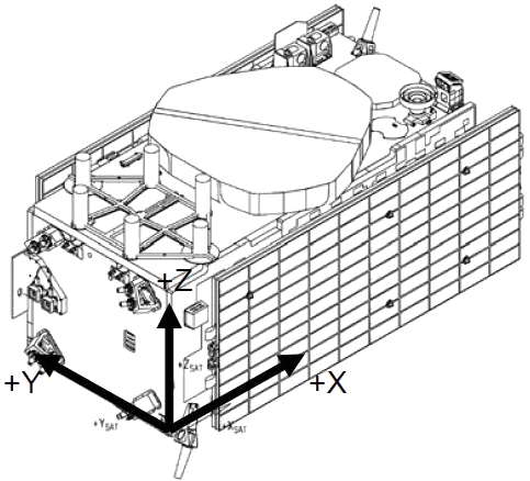
As depicted in the graph above, the Galileo IOV Reference Frame (RF) origin is located at one of the satellite corners. The +Z axis is normal to the separation plane and points to the same direction of the L-Band Navigation Antenna.
The X axis is normal to the clock panel and points towards the clock panel while the Y axis completes the right-handed orthogonal system.
2.2 Galileo FOC (GSAT02)
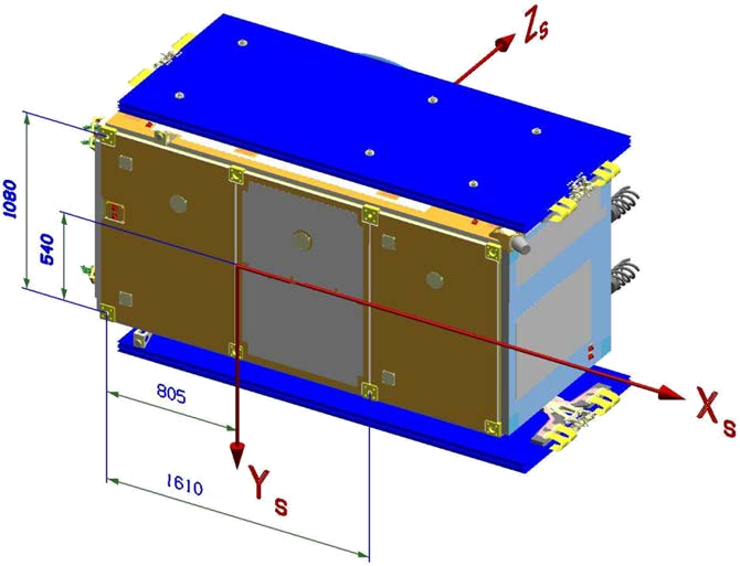
The Mechanical Reference Frame (RF) of the FOC spacecrafts is aligned with the main body axes and originates in the separation plane of dispenser and satellite in the exact middle of the four I/F point centre lines. The + Zs-axis is normal to the separation plane and points towards the L-Band Navigation Antenna.
The + Xs-axis is normal to the clock panel and points towards the clock panel. The + YS-axis completes the right- handed orthogonal system.
3. Attitude Law
3.1 Yaw Steering Law
The nominal Galileo spacecrafts attitude is as follows: the body is fixed in a way it keeps the Z axis towards the Earth Centre (in order to illuminate the Earth with its Navigation Antenna), the Y axis is perpendicular to the Sun and the X axis points towards deep space. Please take into account that this does not meet the GPS block II/IIA attitude convention. It is important to keep the clock panel toward Deep Space so it is protected from the Sun, avoiding thermal variation.
In order to maintain the nominal attitude it is necessary to turn (“yaw“) about its Z axis while rotating its solar panels around the Y axis.
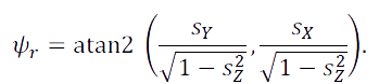
The required rotation is defined with respect to an orbital RF (Reference Frame). The orbital RF has its +Z-axis pointing towards Earth Centre, the +Y-axis perpendicular to the orbital plane (“across- track”), and the +X-axis completing the right-handed orthogonal system and pointing mainly in the flight direction (“along-track"). The yaw steering angle (Ψr) is defined as follows:
3.1.1 IOV Satellites
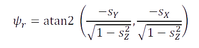
Where
is the reference vector of the Sun in the orbital Reference Frame. Please take into account the term “atan2” means arctangent taking into account the sign of the inputs to determine the proper quadrant of the computed angle.
The position of the Sun is denoted by the following unit vector:
Where β = β(t) denotes the elevation of the Sun with respect to the orbital plane at time “t” and η = η(t) is the geocentric angle between the satellite and the orbit noon (consider “noon” as the point in the satellite orbit where the satellite is closer to the sun) measured in the orbital plane and growing with the spacecraft orbital motion.
In order to keep the yaw change rate (δψr)/(δt) (and also the rate of change of this derivative) low when the Sun is close to the orbital plane (β≃0 deg) while the satellite approaches the orbit noon (η≃0 deg) or midnight (η≃180 deg), the vector ⟶So is substituted by an auxiliary Sun reference vector ⟶SH which allows keeping a minimum angular distance between ⟶S and the spacecraft Z axis.
The region where the auxiliary Sun reference vector is used is:
Where Γ means the sign of SOy at the beginning of the auxiliary region.
3.1.2 FOC Satellites
For the FOC satellites the yaw steering formula is as follows:
Where:
when the Satellite and Sun position vectors are close to colinearity, the following “modified” yaw steering law is used:

Where:
- ψinit is the yaw angle (ψ(t))at the time of the switch over to the modified yaw profile.
- sign is the sign of ψinit
- tmod if the elapsed time since the switch over.
The switch over to the modified yaw steering law takes place when all of the following conditions are met:
- The Sun elevation angle βis smaller than 4.1deg.
- The current colinearity angle ϵis smaller than 10.0deg.
- The colinearity angle for the previous epoch was bigger than 10.0deg.
Note that the colinearity angle (ϵ)is defined as follows:

3.2 Yaw Steering Law (ANTEX Reference Frame Convention)
The Reference Frame used in the ANTenna EXchange (ANTEX) format and in most of the GNSS software packages follows the GPS Block II/IIA attitude conventions. This convention implies that the +X axis points toward the Sun and not towards Deep Space. In order to cope with this 180 degrees reversal in the X axis, it is necessary to change the sign when calculating the yaw steering angle in order to meet the standard. Therefore:
For the IOV satellites, the equation becomes:
For the FOC satellites, the equation becomes:
4. Mass and Centre Of Mass
In the following tables the Mass and Centre Of Mass (COM) of each spacecraft can be found. Initial measurements are performed before each satellite launch, once the spacecraft is fueled. However, please note that both Mass and the Centre Of Mass (COM) may vary depending on the propellant consumption. The updated values are provided below and can also be found on the Laser Ranging Service ILRS website.
4.1 IOV Satellites
COM and mass of IOV satellites as of April 2024:
| GSAT | Mass [Kg] | Centre of Mass | ||
| X [mm] | Y [mm] | Z [mm] | ||
| 0101 | 696.802 | 1205.84 | 628.97 | 553.44 |
| 0102 | 695.318 | 1205.33 | 628.81 | 551.41 |
| 0103 | 697.632 | 1205.29 | 629.58 | 552.81 |
| 0104 | 678.582 | 1204.49 | 630.14 | 552.01 |
4.2 FOC Satellites
COM and mass of FOC satellites as of November 2023:
| GSAT | Mass [Kg] | Centre of Mass | ||
| X [mm] | Y [mm] | Z [mm] | ||
| 0201 | 660.977 | 316.89 | -13.48 | 561.92 |
| 0202 | 662.141 | 311.61 | -12.60 | 562.31 |
| 0203 | 705.685 | 259.54 | -9.24 | 561.17 |
| 0204 | 697.701 | 269.65 | -9.35 | 561.29 |
| 0205 | 708.783 | 258.57 | -9.88 | 565.46 |
| 0206 | 707.734 | 259.24 | -9.51 | 565.27 |
| 0207 | 706.643 | 261.18 | -9.52 | 565.29 |
| 0208 | 709.135 | 261.08 | -10.43 | 565.28 |
| 0209 | 707.879 | 261.50 | -9.60 | 565.00 |
| 0210 | 706.673 | 262.18 | -9.61 | 565.28 |
| 0211 | 707.634 | 263.08 | -10.24 | 565.27 |
| 0212 | 709.858 | 257.28 | -9.88 | 565.27 |
| 0213 | 708.765 | 262.66 | -10.33 | 565.27 |
| 0214 | 709.755 | 261.61 | -9.42 | 565.27 |
| 0215 | 708.500 | 266.80 | -11.31 | 565.35 |
| 0216 | 710.475 | 260.16 | -10.24 | 565.26 |
| 0217 | 710.244 | 262.30 | -10.98 | 565.28 |
| 0218 | 711.514 | 261.15 | -10.70 | 565.28 |
| 0219 | 709.694 | 262.97 | -9.88 | 565.28 |
| 0220 | 710.795 | 262.58 | -9.79 | 565.28 |
| 0221 | 710.703 | 261.70 | -9.33 | 565.27 |
| 0222 | 709.500 | 262.20 | -9.88 | 565.28 |
| 0223 | 711.410 | 262.85 | -10.26 | 565.29 |
| 0224 | 710.670 | 263.41 | -10.06 | 565.27 |
5. Navigation Antenna Phase Centre Corrections
While the satellite motion is defined with respect to the Centre Of Mass (COM), the mean phase Centre is defined with respect to other point, the Antenna Reference Point (ARP). The difference between both points (mean phase centre and ARP) is known as the Phase Centre Offset (PCO).
5.1 Antenna Reference Point (ARP)
As stated above, the antenna PCO for Galileo spacecrafts is different to other GNSS systems in the sense that the offsets are given with respect to a well-determined physical reference point located close to the antenna ground plane: The Antenna Reference Point (ARP). The ARP location with respect to Galileo spacecraft Mechanical and ANTEX Reference Frames can be found in the tables below.
Please note that the Mechanical RF is different between FOC and IOV satellites. Refer to the Reference Frame definition section for more details on this.
5.1.1 IOV Satellites
| GSAT | ARP in Mechanical RF [mm] | ARP in ANTEX RF [mm] | ||||
| X | Y | Z | X | Y | Z | |
| 0101 | 1375.50 | 600.00 | 1100.50 | -169.66 | 28.97 | 547.06 |
| 0102 | 1375.50 | 600.00 | 1100.50 | -170.17 | 28.81 | 549.09 |
| 0103 | 1375.50 | 600.00 | 1100.50 | -170.21 | 29.58 | 547.69 |
| 0104 | 1375.50 | 600.00 | 1100.50 | -171.01 | 30.14 | 548.49 |
5.1.2 FOC Satellites
| GSAT | ARP in Mechanical RF [mm] | ARP in ANTEX RF [mm] | ||||
| X | Y | Z | X | Y | Z | |
| 0201 | 140.00 | 0.00 | 1215.00 | 176.89 | -13.48 | 653.08 |
| 0202 | 140.00 | 0.00 | 1215.00 | 171.61 | -12.60 | 652.69 |
| 0203 | 140.00 | 0.00 | 1215.00 | 119.54 | -9.24 | 653.83 |
| 0204 | 140.00 | 0.00 | 1215.00 | 129.65 | -9.35 | 653.71 |
| 0205 | 140.00 | 0.00 | 1215.00 | 118.57 | -9.88 | 649.54 |
| 0206 | 140.00 | 0.00 | 1215.00 | 119.24 | -9.51 | 649.74 |
| 0207 | 140.00 | 0.00 | 1215.00 | 121.18 | -9.52 | 649.71 |
| 0208 | 140.00 | 0.00 | 1215.00 | 121.08 | -10.43 | 649.72 |
| 0209 | 140.00 | 0.00 | 1215.00 | 121.50 | -9.60 | 650.00 |
| 0210 | 140.00 | 0.00 | 1215.00 | 122.18 | -9.61 | 649.72 |
| 0211 | 140.00 | 0.00 | 1215.00 | 123.08 | -10.24 | 649.73 |
| 0212 | 140.00 | 0.00 | 1215.00 | 117.28 | -9.88 | 649.73 |
| 0213 | 140.00 | 0.00 | 1215.00 | 122.66 | -10.33 | 649.73 |
| 0214 | 140.00 | 0.00 | 1215.00 | 121.61 | -9.42 | 649.73 |
| 0215 | 140.00 | 0.00 | 1215.00 | 126.80 | -11.31 | 649.65 |
| 0216 | 140.00 | 0.00 | 1215.00 | 120.16 | -10.24 | 649.74 |
| 0217 | 140.00 | 0.00 | 1215.00 | 122.30 | -10.98 | 649.72 |
| 0218 | 140.00 | 0.00 | 1215.00 | 121.15 | -10.70 | 649.73 |
| 0219 | 140.00 | 0.00 | 1215.00 | 122.97 | -9.88 | 649.72 |
| 0220 | 140.00 | 0.00 | 1215.00 | 122.58 | -9.79 | 649.72 |
| 0221 | 140.00 | 0.00 | 1215.00 | 121.70 | -9.33 | 649.73 |
| 0222 | 140.00 | 0.00 | 1215.00 | 122.20 | -9.88 | 649.72 |
| 0223 | 140.00 | 0.00 | 1215.00 | 122.85 | -10.26 | 649.71 |
| 0224 | 140.00 | 0.00 | 1215.00 | 123.41 | -10.06 | 649.74 |
Please note that the PCOs in the Galileo ANTEX refer to the ARP, although the ANTEX format strictly requires satellite antenna PCOs to be referred to the COM. This allows updating a single vector each time the Center Of Mass changes.
5.2 Measured Phase Centre Offsets (PCO) and Variations
The Navigation Antenna on-board each satellite has been chamber-calibrated prior to launch for all five carrier signals. The measured PCOs with respect to the ARP are given in the table below.
5.2.1 IOV Satellites
| GSAT | Signal | PCO in Mechanical RF [mm] | PCO in ANTEX RF [mm] | ||||
| X | Y | Z | X | Y | Z | ||
| 0101 | E1 | -0.23 | -0.73 | 264.67 | 0.23 | 0.73 | 264.67 |
| E5a | 0.20 | 3.05 | 244.75 | -0.20 | -3.05 | 244.75 | |
| E6 | 1.33 | -0.85 | 162.76 | -1.33 | 0.85 | 162.76 | |
| E5b | 0.51 | 1.89 | 250.85 | -0.51 | -1.89 | 250.85 | |
| E5 | 0.35 | 2.48 | 245.76 | -0.35 | -2.48 | 245.76 | |
| 0102 | E1 | 1.37 | -1.11 | 295.49 | -1.37 | 1.11 | 295.49 |
| E5a | -0.69 | 0.97 | 232.32 | 0.69 | -0.97 | 232.32 | |
| E6 | 0.96 | -0.13 | 191.26 | -0.96 | 0.13 | 191.26 | |
| E5b | 1.00 | 1.00 | 259.69 | -1.00 | -1.00 | 259.69 | |
| E5 | 0.15 | 0.96 | 243.78 | -0.15 | -0.96 | 243.78 | |
| 0103 | E1 | 2.00 | -0.30 | 258.37 | -2.00 | 0.30 | 258.37 |
| E5a | 0.80 | 1.64 | 244.39 | -0.80 | -1.64 | 244.39 | |
| E6 | 1.30 | -0.54 | 190.22 | -1.30 | 0.54 | 190.22 | |
| E5b | 2.46 | 1.33 | 240.27 | -2.46 | -1.33 | 240.27 | |
| E5 | 1.64 | 1.44 | 240.58 | -1.64 | -1.44 | 240.58 | |
| 0104 | E1 | 1.30 | 0.79 | 242.50 | -1.30 | -0.79 | 242.50 |
| E5a | -0.42 | 2.27 | 257.58 | 0.42 | -2.27 | 257.58 | |
| E6 | 0.56 | 0.41 | 165.96 | -0.56 | -0.41 | 165.96 | |
| E5b | 1.49 | 1.45 | 251.34 | -1.49 | -1.45 | 251.34 | |
| E5 | 0.56 | 1.86 | 252.95 | -0.56 | -1.86 | 252.95 | |
5.2.2 FOC Satellites
| GSAT | Signal | PCO in Mechanical RF [mm] | PCO in ANTEX RF [mm] | ||||
| X | Y | Z | X | Y | Z | ||
| 0201 | E1 | 0.38 | -0.20 | 88.95 | -0.38 | 0.20 | 88.95 |
| E5a | -0.49 | -0.70 | -42.25 | 0.49 | 0.70 | -42.25 | |
| E6 | -0.47 | -0.05 | 37.21 | 0.47 | 0.05 | 37.21 | |
| E5b | -1.40 | -0.14 | 4.99 | 1.40 | 0.14 | 4.99 | |
| E5 | -0.94 | -0.41 | -18.17 | 0.94 | 0.41 | -18.17 | |
| 0202 | E1 | 0.57 | 0.36 | 69.30 | -0.57 | -0.36 | 69.30 |
| E5a | -0.88 | -0.19 | -43.31 | 0.88 | 0.19 | -43.31 | |
| E6 | 0.23 | -0.27 | -7.32 | -0.23 | 0.27 | -7.32 | |
| E5b | -1.29 | 0.00 | 4.53 | 1.29 | 0.00 | 4.53 | |
| E5 | -1.09 | -0.10 | -18.98 | 1.09 | 0.10 | -18.98 | |
| 0203 | E1 | 0.78 | -0.64 | 90.93 | -0.78 | 0.64 | 90.93 |
| E5a | -0.16 | -0.78 | -52.88 | 0.16 | 0.78 | -52.88 | |
| E6 | 0.09 | -0.79 | 19.64 | -0.09 | 0.79 | 19.64 | |
| E5b | -0.82 | -0.71 | -4.05 | 0.82 | 0.71 | -4.05 | |
| E5 | -0.49 | -0.74 | -28.42 | 0.49 | 0.74 | -28.42 | |
| 0204 | E1 | 2.62 | -1.20 | 43.89 | -2.62 | 1.20 | 43.89 |
| E5a | -1.20 | 0.26 | 0.09 | 1.20 | -0.26 | 0.09 | |
| E6 | 0.08 | -1.46 | 20.73 | -0.08 | 1.46 | 20.73 | |
| E5b | -0.67 | 0.40 | -5.34 | 0.67 | -0.40 | -5.34 | |
| E5 | -0.94 | 0.34 | -2.49 | 0.94 | -0.34 | -2.49 | |
| 0205 | E1 | 1.13 | -0.67 | 73.59 | -1.13 | 0.67 | 73.59 |
| E5a | -0.77 | -0.35 | -20.76 | 0.77 | 0.35 | -20.76 | |
| E6 | -1.19 | -0.73 | 51.44 | 1.19 | 0.73 | 51.44 | |
| E5b | -1.51 | 0.00 | 23.40 | 1.51 | 0.00 | 23.40 | |
| E5 | -1.14 | -0.18 | 1.35 | 1.14 | 0.18 | 1.35 | |
| 0206 | E1 | -0.36 | -1.28 | 47.67 | 0.36 | 1.28 | 47.67 |
| E5a | -0.35 | -0.63 | -38.26 | 0.35 | 0.63 | -38.26 | |
| E6 | 0.62 | -1.45 | 32.99 | -0.62 | 1.45 | 32.99 | |
| E5b | -0.86 | -0.96 | 5.99 | 0.86 | 0.96 | 5.99 | |
| E5 | -0.61 | -0.80 | -16.03 | 0.61 | 0.80 | -16.03 | |
| 0207 | E1 | 2.02 | 0.27 | 43.11 | -2.02 | -0.27 | 43.11 |
| E5a | 0.55 | -0.34 | -38.79 | -0.55 | 0.34 | -38.79 | |
| E6 | 1.00 | -0.26 | 24.25 | -1.00 | 0.26 | 24.25 | |
| E5b | 0.27 | -0.15 | 6.51 | -0.27 | 0.15 | 6.51 | |
| E5 | 0.40 | -0.26 | -16.05 | -0.40 | 0.26 | -16.05 | |
| 0208 | E1 | -0.83 | -0.15 | 73.98 | 0.83 | 0.15 | 73.98 |
| E5a | -0.80 | -0.60 | -43.52 | 0.80 | 0.60 | -43.52 | |
| E6 | -0.83 | -1.31 | 25.79 | 0.83 | 1.31 | 25.79 | |
| E5b | -1.46 | -0.66 | 0.02 | 1.46 | 0.66 | 0.02 | |
| E5 | -1.14 | -0.63 | -21.62 | 1.14 | 0.63 | -21.62 | |
| 0209 | E1 | 0.66 | -0.32 | 62.75 | -0.66 | 0.32 | 62.75 |
| E5a | 0.65 | -1.08 | -53.05 | -0.65 | 1.08 | -53.05 | |
| E6 | 0.80 | -0.35 | 29.14 | -0.80 | 0.35 | 29.14 | |
| E5b | -0.08 | -0.30 | -3.14 | 0.08 | 0.30 | -3.14 | |
| E5 | 0.27 | -0.69 | -28.06 | -0.27 | 0.69 | -28.06 | |
| 0210 | E1 | 0.85 | -1.60 | 74.42 | -0.85 | 1.60 | 74.42 |
| E5a | 0.04 | -0.23 | -13.41 | -0.04 | 0.23 | -13.41 | |
| E6 | 0.14 | -0.40 | 40.11 | -0.14 | 0.40 | 40.11 | |
| E5b | -0.66 | -0.63 | 25.61 | 0.66 | 0.63 | 25.61 | |
| E5 | -0.30 | -0.44 | 6.10 | 0.30 | 0.44 | 6.10 | |
| 0211 | E1 | 1.78 | -1.09 | 76.37 | -1.78 | 1.09 | 76.37 |
| E5a | 0.39 | -0.98 | -32.58 | -0.39 | 0.98 | -32.58 | |
| E6 | 1.23 | -1.60 | 33.70 | -1.23 | 1.60 | 33.70 | |
| E5b | 0.08 | -0.97 | 10.41 | -0.08 | 0.97 | 10.41 | |
| E5 | 0.24 | -0.98 | -11.01 | -0.24 | 0.98 | -11.01 | |
| 0212 | E1 | 1.25 | -0.68 | 87.38 | -1.25 | 0.68 | 87.38 |
| E5a | 0.36 | 0.28 | -38.94 | -0.36 | -0.28 | -38.94 | |
| E6 | 0.63 | 0.18 | 29.99 | -0.63 | -0.18 | 29.99 | |
| E5b | -0.51 | 0.31 | 1.47 | 0.51 | -0.31 | 1.47 | |
| E5 | -0.08 | 0.29 | -18.78 | 0.08 | -0.29 | -18.78 | |
| 0213 | E1 | 0.26 | -0.67 | 85.07 | -0.26 | 0.67 | 85.07 |
| E5a | -0.47 | -0.74 | -45.58 | 0.47 | 0.74 | -45.58 | |
| E6 | -0.72 | -1.07 | 23.33 | 0.72 | 1.07 | 23.33 | |
| E5b | -1.27 | -0.24 | 2.39 | 1.27 | 0.24 | 2.39 | |
| E5 | -0.88 | -0.49 | -21.46 | 0.88 | 0.49 | -21.46 | |
| 0214 | E1 | 0.21 | -0.03 | 107.40 | -0.21 | 0.03 | 107.40 |
| E5a | -0.79 | -0.19 | -43.73 | 0.79 | 0.19 | -43.73 | |
| E6 | 0.08 | -1.07 | 32.49 | -0.08 | 1.07 | 32.49 | |
| E5b | -1.18 | 0.10 | 5.02 | 1.18 | -0.10 | 5.02 | |
| E5 | -0.99 | -0.05 | -19.44 | 0.99 | 0.05 | -19.44 | |
| 0215 | E1 | 0.00 | -0.74 | 130.20 | 0.00 | 0.74 | 130.20 |
| E5a | -0.26 | -0.35 | -46.8 | 0.26 | 0.35 | -46.8 | |
| E6 | -0.32 | -0.49 | 43.01 | 0.32 | 0.49 | 43.01 | |
| E5b | -0.84 | 0.25 | 0.12 | 0.84 | -0.25 | 0.12 | |
| E5 | -0.56 | -0.04 | -23.46 | 0.56 | 0.04 | -23.46 | |
| 0216 | E1 | 0.43 | -0.49 | 81.44 | -0.43 | 0.49 | 81.44 |
| E5a | -0.69 | 0.11 | -48.74 | 0.69 | -0.11 | -48.74 | |
| E6 | -0.46 | -0.28 | 28.54 | 0.46 | 0.28 | 28.54 | |
| E5b | -1.22 | 0.41 | -5.45 | 1.22 | -0.41 | -5.45 | |
| E5 | -0.96 | 0.26 | -27.01 | 0.96 | -0.26 | -27.01 | |
| 0217 | E1 | 1.65 | 0.11 | 93.26 | -1.65 | -0.11 | 93.26 |
| E5a | 0.38 | 0.05 | -14.03 | -0.38 | -0.05 | -14.03 | |
| E6 | 1.15 | -0.20 | 23.84 | -1.15 | 0.20 | 23.84 | |
| E5b | -0.03 | 0.50 | 22.22 | 0.03 | -0.50 | 22.22 | |
| E5 | 0.17 | 0.27 | 4.03 | -0.17 | -0.27 | 4.03 | |
| 0218 | E1 | -1.28 | 0.06 | 88.06 | 1.28 | -0.06 | 88.06 |
| E5a | 0.10 | -0.42 | -34.67 | -0.10 | 0.42 | -34.67 | |
| E6 | -0.86 | -1.11 | 42.49 | 0.86 | 1.11 | 42.49 | |
| E5b | -0.97 | -0.41 | 7.19 | 0.97 | 0.41 | 7.19 | |
| E5 | -0.45 | -0.42 | -13.67 | 0.45 | 0.42 | -13.67 | |
| 0219 | E1 | 1.22 | 1.35 | 66.93 | -1.22 | -1.35 | 66.93 |
| E5a | 0.46 | -0.12 | -50.69 | -0.46 | 0.12 | -50.69 | |
| E6 | -0.06 | -0.48 | 34.09 | 0.06 | 0.48 | 34.09 | |
| E5b | -0.14 | -0.25 | -1.38 | 0.14 | 0.25 | -1.38 | |
| E5 | 0.15 | -0.19 | -26.20 | -0.15 | 0.19 | -26.20 | |
| 0220 | E1 | 0.86 | 0.02 | 93.56 | -0.86 | -0.02 | 93.56 |
| E5a | -0.58 | -2.1 | -73.28 | 0.58 | 2.1 | -73.28 | |
| E6 | 0.69 | -0.95 | 16.02 | -0.69 | 0.95 | 16.02 | |
| E5b | -0.46 | -1.18 | -32.16 | 0.46 | 1.18 | -32.16 | |
| E5 | -0.52 | -1.65 | -52.92 | 0.52 | 1.65 | -52.92 | |
| 0221 | E1 | 0.90 | 1.10 | 71.66 | -0.90 | -1.10 | 71.66 |
| E5a | 0.80 | 0.73 | -48.90 | -0.80 | -0.73 | -48.90 | |
| E6 | 0.00 | -0.57 | 5.97 | 0.00 | 0.57 | 5.97 | |
| E5b | -0.09 | 0.37 | -4.94 | 0.09 | -0.37 | -4.94 | |
| E5 | 0.35 | 0.54 | -26.89 | -0.35 | -0.54 | -26.89 | |
| 0222 | E1 | -1.12 | -0.21 | 81.77 | 1.12 | 0.21 | 81.77 |
| E5a | -0.82 | -1.53 | -41.14 | 0.82 | 1.53 | -41.14 | |
| E6 | -0.93 | -1.66 | 30.35 | 0.93 | 1.66 | 30.35 | |
| E5b | -1.73 | -1.43 | -0.42 | 1.73 | 1.43 | -0.42 | |
| E5 | -1.29 | -1.49 | -20.81 | 1.29 | 1.49 | -20.81 | |
| 0223 | E1 | 0.60 | 0.62 | 79.86 | -0.60 | -0.62 | 79.86 |
| E5a | -1.19 | 0.65 | -43.21 | 1.19 | -0.65 | -43.21 | |
| E6 | 0.21 | -0.12 | 16.81 | -0.21 | 0.12 | 16.81 | |
| E5b | -2.52 | 1.10 | 4.04 | 2.52 | -1.10 | 4.04 | |
| E5 | -1.88 | 0.87 | -19.51 | 1.88 | -0.87 | -19.51 | |
| 0224 | E1 | 0.77 | -1.01 | 70.99 | -0.77 | 1.01 | 70.99 |
| E5a | -0.65 | -1.32 | -66.39 | 0.65 | 1.32 | -66.39 | |
| E6 | -0.22 | -1.54 | 10.30 | 0.22 | 1.54 | 10.30 | |
| E5b | -0.98 | -0.53 | -16.95 | 0.98 | 0.53 | -16.95 | |
| E5 | -0.82 | -0.93 | -41.8 | 0.82 | 0.93 | -41.8 | |
5.3 ANTEX PCVs
The variation of the electrical phase centre of the antenna with respect to the mean phase centre, for a given direction, is called “Phase Centre Variation” (PCV). Direction-Dependant PCVs can be found in the GALILEO ANTEX file. In order to obtain the ANTEX file please click on the following link.
For GSAT01 (IOV) the PCVs are given for a 181 x 15 grid of azimuth and nadir angle pairs with a step size of 2° in azimuth and 1° in nadir. For GSAT02 (FOC) the PCVs are given for a 73 x 41 grid of azimuth and nadir angle pairs with a step size of 5° in azimuth and 0.5° in nadir.
6. Geometry
The Galileo spacecraft is a typical “box-wing” type satellite, consisting of a central cube (the “box”) and two rectangular solar panels (the “wings”) attached to it. Due to the way the attitude of the spacecraft is controlled, only three of the six satellite panels are actually exposed to solar radiation: the –X panel, the –Z panel and the +Z panel. (Note EOL means “End Of Life” and BOL means “Beginning Of Life”).
The optical properties coefficients are: α ≡ absorption coefficient, ρ ≡ specular reflection coefficient, δ ≡ diffuse reflection coefficient.
The surface area of each solar array amounts to 5.41 m2 (= 5.000 m x 1.082 m).
6.1 IOV Satellites
| Dimension of the Box with respect to the Mechanical RF | Surface areas of the Box |
| ΔX = 2.611m | ±X - panel = 1.32m2 |
| ΔY=1.149m | ±Y - panel = 3.00m2 |
| ΔZ=1.149m | ±Z - panel = 3.00m2 |
| Surface | Material 1 | Area [m2] | BOL & EOL | |||
| α | ρ | δ | ||||
| Box | -X | Carbon filled Kapton (external MLI) | 1.32 | 0.94 | 0.00 | 0.06 |
| +X | 0.54 | |||||
| +Y | 1.00 | |||||
| -Y | 1.03 | |||||
| +Z | 1.72 | |||||
| -Z | 3.00 | |||||
| Wing | +Y | Sollar Cells | 3.88 | 0.92 | 0.08 | 0.00 |
| -Y | 3.88 | |||||
| Surface | Material 2 | Area [m2] | BOL | EOL | |||||
| α | ρ | δ | α | ρ | δ | ||||
| Box | -X | - | - | - | - | - | - | - | - |
| +X | Optical surface radiator | 0.78 | 0.10 | 0.72 | 0.18 | 0.25 | 0.60 | 0.15 | |
| +Y | 2.00 | ||||||||
| -Y | 1.97 | ||||||||
| +Z | Germanium coated black Kapton foil | 1.28 | 0.57 | 0.22 | 0.21 | 0.57 | 0.22 | 0.21 | |
| -Z | - | - | - | - | - | - | - | - | |
| Wing | +Y | Kapton HN (Insulation layer) | 1.53 | 0.90 | 0.10 | 0.00 | 0.90 | 0.10 | 0.00 |
| -Y | 1.53 | ||||||||
6.2 FOC Satellites
| Dimensions of the Box with respect to the Mechanical RF | Surface areas of the Box |
| ΔX = 2.530m | ±X − panel = 1.320m2 |
| ΔY = 1.200m | ±Y − panel = 2.783m2 |
| ΔZ = 1.100m | ±Z − panel = 3.036m2 |
| Surface | Material | Area [m2] | α[ − ] | ρ[ − ] | δ[ − ] | |
| Box | +X | A | 0.440 | 0.93 | 0.00 | 0.07 |
| C | 0.880 | 0.08 | 0.73 | 0.19 | ||
| -X | A | 1.320 | 0.93 | 0.00 | 0.07 | |
| +Y | A | 1.129 | 0.93 | 0.00 | 0.07 | |
| C | 1.654 | 0.08 | 0.73 | 0.19 | ||
| -Y | A | 1.244 | 0.93 | 0.00 | 0.07 | |
| C | 1.539 | 0.08 | 0.73 | 0.19 | ||
| +Z | A | 1.053 | 0.93 | 0.00 | 0.07 | |
| B | 1.969 | 0.57 | 0.22 | 0.21 | ||
| -Z | A | 2.077 | 0.93 | 0.00 | 0.07 | |
| C | 0.959 | 0.08 | 0.73 | 0.19 | ||
| Wing | +SA | E | 3.880 | 0.92 | 0.08 | 0.00 |
| D | 1.530 | 0.90 | 0.10 | 0.00 | ||
| -SA | E | 3.880 | 0.92 | 0.08 | 0.00 | |
| D | 1.530 | 0.90 | 0.10 | 0.00 | ||
7. Laser Retro Reflector Location
The center of phase of the LRR (Laser Retro Reflector) is provided in the tables below.
7.1 IOV Satellites
| GSAT | LRR in Mechanical RF [mm] | LRR in ANTEX RF [mm] | ||||
| X | Y | Z | X | Y | Z | |
| 0101 | 2298.00 | 595.00 | 1174.00 | -1092.16 | 33.97 | 620.56 |
| 0102 | 2298.00 | 595.00 | 1174.00 | -1092.67 | 33.81 | 622.59 |
| 0103 | 2298.00 | 595.00 | 1174.00 | -1092.71 | 34.58 | 621.19 |
| 0104 | 2298.00 | 595.00 | 1174.00 | -1093.51 | 35.14 | 621.99 |
7.2 FOC Satellites
| GSAT | LRR in Mechanical RF [mm] | LRR in ANTEX RF [mm] | ||||
| X | Y | Z | X | Y | Z | |
| 0201 | -703.00 | -27.50 | 1120.45 | 1019.89 | 14.02 | 558.53 |
| 0202 | -703.00 | -27.50 | 1120.45 | 1014.61 | 14.90 | 558.14 |
| 0203 | -703.00 | -27.50 | 1120.45 | 962.54 | 18.26 | 559.28 |
| 0204 | -703.00 | -27.50 | 1120.45 | 972.65 | 18.15 | 559.16 |
| 0205 | -703.00 | -27.50 | 1120.45 | 961.57 | 17.62 | 554.99 |
| 0206 | -703.00 | -27.50 | 1120.45 | 962.24 | 17.99 | 555.19 |
| 0207 | -703.00 | -27.50 | 1120.45 | 964.18 | 17.98 | 555.16 |
| 0208 | -703.00 | -27.50 | 1120.45 | 964.08 | 17.07 | 555.17 |
| 0209 | -703.00 | -27.50 | 1120.45 | 964.50 | 17.90 | 555.45 |
| 0210 | -703.00 | -27.50 | 1120.45 | 965.18 | 17.89 | 555.17 |
| 0211 | -703.00 | -27.50 | 1120.45 | 966.08 | 17.26 | 555.18 |
| 0212 | -703.00 | -27.50 | 1120.45 | 960.28 | 17.62 | 555.18 |
| 0213 | -703.00 | -27.50 | 1120.45 | 965.66 | 17.17 | 555.18 |
| 0214 | -703.00 | -27.50 | 1120.45 | 964.61 | 18.09 | 555.18 |
| 0215 | -703.00 | -27.50 | 1120.45 | 969.80 | 16.19 | 555.10 |
| 0216 | -703.00 | -27.50 | 1120.45 | 963.16 | 17.26 | 555.19 |
| 0217 | -703.00 | -27.50 | 1120.45 | 965.30 | 16.52 | 555.17 |
| 0218 | -703.00 | -27.50 | 1120.45 | 964.15 | 16.80 | 555.18 |
| 0219 | -703.00 | -27.50 | 1120.45 | 965.97 | 17.62 | 555.17 |
| 0220 | -703.00 | -27.50 | 1120.45 | 965.58 | 17.71 | 555.17 |
| 0221 | -703.00 | -27.50 | 1120.45 | 964.70 | 18.17 | 555.18 |
| 0222 | -703.00 | -27.50 | 1120.45 | 965.20 | 17.62 | 555.17 |
| 0223 | -703.00 | -27.50 | 1120.45 | 965.85 | 17.24 | 555.16 |
| 0224 | -703.00 | -27.50 | 1120.45 | 966.41 | 17.45 | 555.19 |
8. Satellite Group Delay
The satellite group delay is the total amount of time it takes to a signal of a particular bandwidth to start out from the on-board frequency oscillator, travel through each code generator, modulator, transmitter, multiplexer, and finally emerge from the satellite’s antenna. Since the group delays among the various signal paths within the satellite are not the same, signals do not exactly emerge from the transmitting antenna at the same time. The difference between the group delay of the radiated signals of two carrier frequencies f1 and f2 is what is commonly referred to as satellite group delay differential or Differential Code Bias (DCB). The results in the tables below are just applicable for the IOV satellites.
8.1 Measured Satellite Group Delay
The Galileo IOV satellite group delays have been measured on-ground by the spacecraft manufacturer for all three signal bands (E1, E5, and E6) and both on-board subsystems (“primary” and “redundant”). The results are listed in the table below.
| GSAT | Primary [ns] | Redundant [ns] | ||||
| E1 | E5 | E6 | E1 | E5 | E6 | |
| 0101 | 1214.8 | 1205.1 | 1208.9 | 1215.2 | 1204.9 | 1206.7 |
| 0102 | 1218.9 | 1212.0 | 1211.2 | 1218.9 | 1212.5 | 1211.7 |
| 0103 | 3149.3 | 3146.9 | 3149.8 | 3150.3 | 3149.3 | 3150.1 |
| 0104 | 3150.0 | 3148.1 | 3148.3 | 3151.9 | 3150.7 | 3149.8 |
8.2 Differential Code Bias
Median values and standard deviations of these (hourly) DCBs estimates are given in the Table below. The standard deviations point to a DCB stability of about σ = ±0.1m (0.3 ns). Evidence for the existence of thermal-dependent fluctuations, as detected in tri-carrier combinations computed for the GPS Block IIF spacecraft series while passing through eclipse season, was not found.
>
| GSAT | E1-E5a | E1-E5b | E1-E6 | |||
| [ns] | [m] | [ns] | [m] | [ns] | [m] | |
| 0101 | 9.71±0.38 | 2.910±0.115 | 9.77±0.32 | 2.929±0.095 | 6.32±0.37 | 1.894±0.111 |
| 0102 | 6.97±0.41 | 2.089±0.122 | 6.87±0.33 | 2.060±0.099 | 7.41±0.30 | 2.220±0.90 |
| 0103 | 2.15±0.48 | 0.644±0.144 | 2.11±0.39 | 2.634±0.117 | -0.77±0.31 | -0.230±0.094 |
| 0104 | 2.14±0.39 | 0.641±0.116 | 2.15±0.50 | 0.644±0.150 | 1.82±0.25 | 0.546±0.076 |
9. Glossary
| Name | Description |
| Antenna Reference Point (ARP) | Physical reference point located close to the antenna ground plane, used to refer the PCO in the Galileo data |
| Antenna Phase Centre Offset (PCO) | Difference between the position of the mean phase centre and the ARP |
| Differential Code Bias (DCB) | Difference between the group delay of the radiated signals of two carrier frequencies f1 and f2. |
| Mean Phase Centre | Point for which the phase of the signal shows the smallest (in the sense of “least- squares”) Phase Centre Variation (PCV) for a given nadir angle interval |
| Phase Centre Variation (PCV) | Variation of the Phase Centre location as a function of the direction of the outgoing signal for a specific frequency |
| FOC | Full Operational Capabilities |
| IOV | In Orbit Validation |
| COM | Centre Of Mass |
10. GNSS Bibliography
[1] European GNSS (Galileo) Open Service Signal In Space Interface Control Document. European Union, 2016.
[2] B. Hofmann-Wellenhof. Global Positioning System Theory and Practice. Springer, 2001.
[3] J.M. Juan Zornoza J. Sanz Subirana, M. Hernández-Pajares. GNSS DATA PROCESSING. European Space Agency, 2013.
[4] A. Leick. GPS Satellite Surveying. Wiley-Interscience, 1994.